Basics of Machine Elements
Kone-elimien perusteita
1. Bearing Dimensioning.
2. Calculated Bearing Lifetime.
3. Product Line Formation of the Screws.
4. Screw Forces and Torque
5. Screw Head Dimensions
6. Screw Head Widths
7. Metric Standard Nuts
8. Formation of the Steel Rope Product Series
8.1 Incandescent Light Bulb
8.2 Steel
8.3 Steel Rope
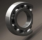
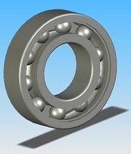
1. Bearing Dimensioning
Bearing dimensioning is often a simple task by calculation. In practice, the bearing dimensionings are the basic cases, comparing the bearing load to the tabled C value. Normally the bearing is affected by axis and radial forces, which are included in the EP-calculation.
Bearing Dimensioning as a Reasoning Task
 Bearing calculation examples are compared with the bearing calculation program. The difference is small to EP-calculation, but the calculation speed is high. By understanding the proportionality of the bearings, the bearings range of the products offers the consistent reliability. The design of the bearings is associated with steels, both having the strength basis. Bearing calculation examples are compared with the bearing calculation program. The difference is small to EP-calculation, but the calculation speed is high. By understanding the proportionality of the bearings, the bearings range of the products offers the consistent reliability. The design of the bearings is associated with steels, both having the strength basis.
Companies rarely have standardised the selection of the components. However, there is continuous requirement to inventory items value reduction. This work is often left to commercial decision-makers, without connection to the design values.
Bearing Values of the External Dimensions
Calculation shows a harmonic series of bearing of their external dimensions => dynamic bearing values are determined throug the bearing dimensions => dynamic bearing value determines the bearing lifetime => through tangible dimensions of the bearing, the not tangible lifetime. (1058)
2. Calculated Bearing Lifetime
 The table shows the calculated lifetime of the devices commonly required. EP-calculation calculates the lifetime of the bearings and connects the data to devices functional age. The table shows the calculated lifetime of the devices commonly required. EP-calculation calculates the lifetime of the bearings and connects the data to devices functional age.
This is because, the device structures are dimensioned having the stress level at which fatigue does not appear in the product life-term load number. In practice, the stress level is equal to one that fatigue does not appear from the load, ie the machine wears without getting tired.
Bearing Lifetime in Hours
Household appliances generally 500 - 2 000
Devices which are used occasionally 2 000 - 4 000
- cars
Elevators (Lifts) 8 000 - 12 000
Conveyors and small electric motors 12 000 - 20 000
Several track-laying vehicles 20 000 - 40 000
Large electric motors and pumps 80 000 - 200 000
Power Plant Generators
Ship propellers bearings
Lifetime Kilometers
Wheel bearings on a road vehicle
- Passenger vehicles (100 000) 200 000
At present, many car models are not performing the required service life in km. This is due to the bearings lack of protection against water and dirt.
- Trucks and buses 300 000 ...
Railway carriages over short distances 800 000 - 1 500 000
Railway carriages on long journeys 3 000 000
Locomotives over short distances 3 000 000 - 4 000 000
Electric and diesel locomotives long distances 3 000 000 - 5 000 000
Bearing lifetime in hours or kilometers can be set relative. This is because it becomes easier comparison between the devices. The ratio between one hour (60 minutes) and 100 km is 1.618, ie the golden section (1.9% accuracy). Table above, such as bearing manufacturers in the average presented.
(358
3. Product Line Formation of the Screws
Metric Screws
Consider how the screw products comply with the golden section ratio coefficient of 1.618 and the sequence of coefficient of 1.25. At first, it is known as the screws M4 and M5 and of this may indicate. The size of screw will grow by 5 / 4 = a factor of 1.25. In practice, the M20 screw is the maximum which is normally used. Larger screws have slightly different dimensions, but this is not significant.
4 - 5 - 6(,3) - 8 - 10 - 12(.5) - 16 - 20 - 25
1.25 x 4 = 5 mm
1.25 x 5 = 6 mm
1.25 x 6,3 = 8 mm
1.25 x 8 = 10 mm
1.25 x 10 = 12 mm
1.25 x 12,5 = 16 mm
1.25 x 16 = 20 mm
Golden Section Ratio 1,618
4 mm screw: 4 x 4 = 16
5 mm screw: 5 x 5 = 25 => 25 / 16 = 1.6(18)
8 mm screw: 8 x 8 = 64
10 mm screw: 10 x 10 = 100 => 100/64 = 1.57 x 1.03 = 1.6(18)
16 mm screw: 16 x 16 = 256
20 mm screw: 20 x 20 = 400 => 400 / 256 = 1.57 x 1.03 = 1.6(18)
The following calculated screw sizes are M25, M32 and M40. In practice, the corresponding screws are M24, M33 and M42. Of these, M33 screw sizes are not favored, although the size of the screws are still available. Similarly, M40 mm screw size has been selected size of 42 mm. This has its own reasons, which can not be guessed or determined in this context.
The quality features of the product are usability and safety. We find the screw sizes to comply with the Golden Section Ratio, which ensures safety. When calculating the stresses, they are found to be at the same level for all screw sizes.
0.785 x1.25 x 1.03 = 1
0.785 is the square and circular cross-sectional area ratio
0.785 is the specific gravity of steel
We calculated the size formation of the screws & the strength formation of the product. As all phenomena are derived from the simple formula E = m c c, the products are determined by a simple product, such as a screw. Prior to this, however, is the need to understand many things. I am writing of this on my pages. (991)
4. Screw Forces and Torque
Metric standard thread
640 N/mm2 = Material 0.2 -limit
0.15 µ = Friction factor of the thread
0.15 µ = Friction factor of the nut
60º = Flank angle of the thread
0.4 - 0.5 - 0.63 - 0.8 - 1 - 1.25 - 1.6 - 2.0
M4 - M5 - M6 - M8 - M10 - M12 - M16 - M20
Tensile tress Clamping force Needed tightening
max. max. torque
N / mm2 N Calculation Nm Calculation
M4 559.36 4911 Given value 2.6 Given value
M5* 562.61 7989 1.618 x 4911= 7946 5.0 21 x 2.6 = 5.2
M6** 561.22 11280 1.6182 x 4911= 12857 8.6 22 x 2.6 = 10.4
M8 563.34 20618 1.618 3 x 4911= 20802 20.7 2 3 x 2.6 = 20.8
M10 564.52 32742 1.6184 x 4911= 33658 40.2 24 x 2.6 = 41.6
M12*** 565.26 47652 1.6185 x 4911= 54458 683 25 x 2.6. = 83.2
M16 568.52 89257 1.6186 x 4911= 88113 165.0 26 x 2.6 = 166.4
M20 568.52 139286 1.6187 x 4911= 142567 322.5 27 x 2.6 = 332.8
M24 568.52 200686 1.6188 x 4911= 230674 554.6 28 x 2.6 = 665.6
* Fibonacci Numbers start 1 - 1 - 2 ... Pascal's Triangle has the same form.
The second is twice the smallest 1 + 1 = 2
2.6 x 2 = 5.0 (not decimal accuracy)
** On the ratio queue, the screw size is M6.3 (0.5 - 0.6.3 - 0.8), which is not the case. This can convert to M6 screw by simplified calculation.
(6/6.3)4 x 12857 = 10577 (6/6.3)5 x10.4 = 8.2
(24/25)4 x 230674 = 195922 (24/25)5 x 665.6 = 542.7
2 x surface area = 4 2 x surface area + moment = 5
*** On the ratio queue, the screw size is M12.5 (0.8 - 1 - 1.25 - 16), which is not the case.
(12/12.5)4 x 54458 = 46254 (12/12.5)5 x 83.2 = 67.8
4.1 Example:
M16 screw clamping force according to the table is 89257 N. Wanted M16 bolt clamping force is 25 % lower, in other words 89 257 N /1.25 = 714 056 N
=> Tightening torque = 165 Nm /1.25 = 132 Nm
(390)
5. Screw Head Dimensions
Whe one of dimensions is known, others are known.
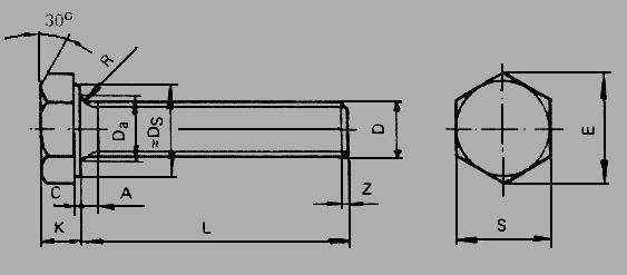
1 + 1.618 = 2.618
S E K
M4 7.0 7.74 1.11 x 7.0 = 7.77 2.8 7.70 / 2.618 = 3.0
M5 8.0 8.87 1.11 x 8.0 = 8.86 3,5 8.87 / 2.618 = 4.0
M6 10 11.05 1.11 x 10 = 11.20 4.0 11.05 / 2.618 = 4.2
M8 13 14.38 1.11 x 13 = 14.43 5.5 14.48 / 2.618 = 5.5
M10 17 18.90 1.11 x 17 = 18.87 7.0 18.90 / 2.618= 7.2
M12 19 21,10 1.11 x 19 = 21.09 8.0 21.10 / 2.618 = 8.1
M16 24 26.75 1.11 x 24 = 26.64 10.0 26.75 / 2.618 = 10.2
M20 30 33.53 1.11 x 30 = 33.30 13.0 33.53 / 2.618 = 12.8
M24 36 39.98 1.11 x 36 = 39.96 15.0 39.98 / 2.618 = 15.2
2 x 3.14 / 1.25 = 5
S E K
M4 7,0 7.74 2,8 (7,0 + 7.74) / 5 = 3.0
M5 8,0 8.87 3.5 (8,0 + 8.87) /5 = 3.4
M6 10 11.05 4,0 (10 + 11.05) /5 = 4.2
M8 13 14.38 5.5 (13 + 14.48) /5 = 5.5
M10 17 18.90 7.0 (17 + 18.90) /5 = 7.2
M12 19 21.10 8.0 (19 + 2.618) /5 = 8.0
M16 24 26.75 10.0 (24 + 2.618) /5 = 10,2
M20 30 33.53 13.0 (30 + 33.53) /5 = 12.7
M24 36 39.98 15.0 (36 + 39.98) /5 = 15.2
(212)
6. Screw Head Widths
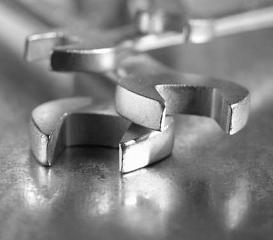
Of the screw-heads we do know that 4 mm screw width across flats to be 7 mm and 5 mm screw 8 mm.
7 mm / 4 mm = 1.75
8 mm / 5 mm = 1.60
Golden Ratio
We define the width across flats, according to Golden Ratio 1.6(18);
4 mm x 1.618 = 6.472 - 5 mm x 1.618 = 8.09
6.472 mm => 7.0 mm
8.09 => 8.0 mm
Metric Srews
4 - 5 - 6 - 8 - 10 - 12 - 16 - 20 Screws mm
7 - 8 - 10 - 13 - 17 - 19 - 24 - 30 Width across flats of the screw mm
4 x 1.6(18) = 6.4 mm
5 x 1.6(18) = 8.0 mm
6 x 1.6(18) = 96 mm.
8 x 1.6(18) = 12.8 mm
10 x 1.6(18) = 16 mm
12 x 1.6(18) = 19.2 mm
16 x 1.6(18) = 25.6 mm
20 x 1.6(18) = 32 mm
10 mm screw; the width across flats of the screw could be 16 mm, instead of the 17 mm.
16 mm screw; the width across flats of the screw is smaller than defined 25.6 mm.
20 mm screw is by calculating defined to 32 mm, but selected 30 mm.
All defined widths fill up the requirements of the screw.
7. Metric Standard Nuts
0,8 - 1,0 - 1,1(2) - 125
Nut dimensions can be calculated as the Equivalent Proportional Calculation.
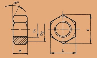

Metric nut
S E M
M3 5.5 6.08 1.11 x 5.5 = 6.11 2.4 0.8 x 3.0 = 2.4
M4 7.0 7.74 1.11 x 7.0 = 7.77 3,2 0.8 x 4.0 = 3.2
M5 8.0 8.87 1.11 x 8.0 = 8.86 4,0 0.8 x 5.0 = 4.0
M6 10 11.05 1.11 x 10 = 11.20 5,0 0.8 x 6.0 = 4.8
M8 13 14.38 1.11 x 13 = 14.43 6.5 0.8 x 8.0 = 6.4
M10 17 18.90 1.11 x 17 = 18.87 8,0 0.8 x 10 = 8.0
M12 19 21.10 1.11 x 19 = 21.09 10.0 0.8 x 12 = 9.6
M16 24 26.75 .1.11 x 24 = 26.64 13.0 0,8 x 16 = 12.8
M20 30 33.53 1.11 x 30 = 33.30 16.0 0.8 x 20 = 16.0
M24 36 39.98 1.11 x 36 = 39.96 19.0 0.8 x 24 = 19.2
174.56 174.36
The calculation has the idea of how almost anything can be calculated through proportionality, when you know the procedure for the calculation. For this reason, should be familiar with physics, strength calculation, and keep your open mind. What about the dimensions of the M39 screw, if you know the dimensions of the screw M3? (918)
S E M
M3 5.5 6.08 1.11 x 5.5 = 6.11 2.4 0.8 x 3.0 = 2.4
M39 60 69.3 31 0.8 x 39 = 31.2
1.2511x 55 = 64
1.2511 x 6.08 = 70.8
1.2511 x 2.4 = 27.9
Steps
... M24 - M30 - M39
9. 10. 11.
8. Formation of the Steel Rope Product Series
This time we look at the steel rope 6x26 Warrington-seale and we find that the behavior as a phenomenon does not differ from a incandescent bulb.
Steel rope - Light from lamp
By hand touchable - Not by hand touchable
____________________________________________________
Dimensionalities
Length - Area - Volume - Time
Speed of light is area c2
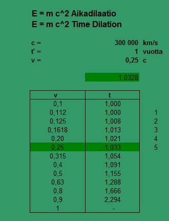
Why did I chose this time steel rope, due to the fact that I finished the previous writing to visual geometry patterns. The square and the circle area ratio are defined by time dilation and the the area of the unit circle is the specific gravity of steel. Calculation throug figures would not be possible without this connection.
1 / (1.25 x 1.03) = 0.78
8.1 Incandescent Light Bulb

Saamme energian auringosta. Aurinkoa emme voi tarkastella, joten on luotava pienimuotoinen avaruus. Tähän tarkoitukseen otamme hehkulampun kuvassa. Valo lampussa syntyy, kun hehkulanka kuumennetaan korkeaan lämpötilaan sähkövirran avulla, kunnes lanka hehkuu. Hehkulampuilla on valon tuottamisessa huono hyötysuhde, noin 3 ... 5%, jolloin valo on lämmittämisprosessissa syntyvä kitka.
We get the energy from the Sun. We cannot look at the Sun, so we need to create a small-scale space. To this we take the light bulb in the image. An electric light inside the lamp is produced with a filament wire heated to a high temperature by an electric current through it, until it glows.
Most incandescent bulbs convert 3 - 5% of the energy they use into visible light, then the light is friction of the heating process.
100 / 1.0328 = 96.82 %
Universal friction 1.033
8.2 Steel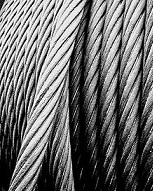
Wikipedia
Steel is an alloy of iron and carbon that is widely used in construction and other applications because of its hardness and tensile strength. Carbon, other elements, and inclusions within iron act as hardening agents that prevent the movement of dislocations that naturally exist in the iron atom crystal lattices. The carbon in typical steel alloys may contribute up to 2.1% of its weight.
Varying the amount of alloying elements, their formation in the steel either as solute elements, or as precipitated phases, retards the movement of those dislocations that make iron so ductile and weak, and thus controls qualities such as the hardness, ductility, and tensile strength of the resulting steel. Steel's strength compared to pure iron is only possible at the expense of ductility, of which iron has an excess.
8.3 Steel Rope
The steel rope is intended for supporting. The analysis shows a range of the steel rope formed the same way as in the previous example. Steel Rope values are in the revised tables.
Diameter Weight
D mm kg/100 m
10 38.0
12 54.7 54.7/38.0 = 1.779
16 97.3 97.3/54.7 = 1.772
20 152.0 152/97.3 = 1.562
24 219.0 219/152 = 1.441
32 389.0 389/219 = 1.777
40 608,0 608/389 = 1.562
Average = 1.649
1.618 x 1.0165 = 1.645
1 + (0.033/2) = 1.0165
10 - 12.5 - 16 - 20 - 25 - 32 - 40
.
The rule in the two-dimensionality of the universe; twice as far to be four times larger. Status value = 10 => 16 is two times higher.
4 x 38 kg/100 m = 152 kg/100 m
16 x 38 kg/100 m = 608 kg/100 m
6x26 Warrington-seale (the breaking strength of the yarn 15,7 kN/cm2 )
Tabled data
D mm kN/cm2
10 55.9
12 80.6 8,06/5,59 = 1.442
16 143.0 143/80,6 = 1.774
20 224.0 224/143 = 1.567
24 322.0 322/224 = 1.438
32 573.0 573/322 = 1.780
40 895.0 895/573 = 1.562
Yhteensä = 1.593
1.618 / 1.0165 = 1.591
1 + (0.033/2) =1.0165
Minimum breaking load is to be attained or surpassed during the tensile-test.
4 x 55.9 = 223.6 kN/cm2
16 x 55.9 kN/cm2 = 894.4 kN/cm2
(1.649 + 1.593) /2 = 1.62 = Golden ratio 1.618
1.033 x 1.593 = 1.645
Finally
Determining the bulb radius to the relative value of 1.
The spherical body surface area A = 4 Pi r2
r1 => A = 4 pii 12 = 12,56 Unit area
r2 => A = 4 pii 22 = 50,24 Unit area
r4 => A = 4 pii 42 = 200,96 Unit area
In the formula, the radius increases twice bigger, the surface area will increase by a factor of four. Thinking about the heat evenly distributed onto the surface area. When the radius (r) increases twice bigger, decreases the amount of heat on the surface area to 1/4 per unit area. In the end the rope and lamp values formation does not differ from each other. The same goes well, as long as everything is derived from the formula E = mcc
Note! Solar constant magnitude near the outer surface of the Earth's atmosphere is 1,37 kW/m2

21.6.2018*08:00 (265 - 845)
www.karikolehmainen.com
|